這個指令會對輸入資料進行邏輯判斷再藉由資料線將真/偽結果送出.輸入資料(真或是偽)可以由單選按鍵指定或是由資料線動態輸入
This block performs a logical operation on its inputs and sends out the true/false answer by a data wire. The inputs (which must also be “true” or “false”) can be set using the radio buttons or supplied dynamically from data wires.
邏輯指令在輸入或輸出時只使用"真","偽"值.通常使用數字"1"代表真,數字"0"代表偽.
The Logic block uses only two possible values, “true” and “false,” for both input and output. Often these values are written as the numbers “1” and “0” where any true statement is written as a 1 and any false statement is written as a 0.
這樣數字系統對電腦來說是容易理解且輕易地以"二進位"來紀錄資料.並可以從1與0的轉換處理複雜的數字跟程式.
This system is very simple for computers to understand because computer memory has an easy time recording “binary” values, values that come in only two states like the 1 and 0. Computers handle more complicated numbers and equations by building up from 1 and 0.
![]() 注意: 可以用數字1和0當作此指令的輸入值,但必須使用邏輯資料線.
注意: 可以用數字1和0當作此指令的輸入值,但必須使用邏輯資料線.
Note: you can use the values 1 and 0 as input to this block but they must be supplied by logic data wires.
四種邏輯運算(而且, 或者, 互斥與反相)分別做下列的比較:The four logical operations that this block can perform allow you to perform a series of comparisons. The details of these operations (And, Or, Xor, and Not) are described below.

當邏輯指令放在工作區上時,會自動打開兩個輸入埠和三個輸出埠.輸入埠必須用資料線與其他指令連接.除非用單選按鍵來指定
A Logic block dropped into the work area will open with two input ports and three output ports. The input ports will have to be connected to other blocks using data wires (except when one of them is supplied by a constant value that you set with radio buttons).邏輯運算的結果會從最下方的輸出埠送出.而其他兩個輸出埠會傳遞出相對應的輸入值.如果需要可以用來傳遞輸入值到其他指令.(參考下方的資料集線器說明).
Output from the logical operation will be delivered from the bottommost output plug; connect this plug using a data wire to another block’s data hub. The two output plugs opposite the input plugs allow you to pass the input values on to other blocks if this is necessary. (See the Data Hub section below for more information.)
設定邏輯指令
Configuring the Logic Block
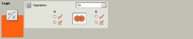
- 在輸入A或輸入B上使用單選按鍵來指定數值或是用資料線來輸入.
Use the radio buttons to choose inputs A and B or let input data wires supply the input values dynamically. - 共有四種邏輯判斷方式可供選擇.
The pull-down menu will let you choose from four operations you can perform on the inputs: - "而且"運算 An “And” Operation
- "或者"運算 An “Or” Operation
- "互斥"運算 An “Xor” Operation
- "反相"運算 A “Not” Operation

而且"運算
“And” Operation
而且"運算只有在兩個輸入值都為"真"時,輸出結果才為"真". 其他的情況均是"偽".
With the “And” operation, if your two input values are both “true,” then the output is also equal to “true”; in all other cases the output will be “false.”
使用"邏輯表"來解釋會較清楚.
This is easy to understand if you look at a “logic table”:
| 輸入A Input A | 輸入B Input B | 輸出 Output |
| 偽 False (0) | 偽 False (0) | 偽 False (0) |
| 偽 False (0) | 偽 True (1) | 偽 False (0) |
| 真 True (1) | 偽 False (0) | 偽 False (0) |
| 真 True (1) | 真 True (1) | 真 True (1) |
只有兩個輸入值為"真"時,答案才為"真",其他例子的輸出皆為"偽".
You can see that only when both input values are equal to “true” is the answer “true”; in all other cases the output is value is “false.”

"或者"運算 “Or” Operation
或者"運算在一個或兩個輸入值為"真"時,輸出結果就為"真".
With the “Or” operation, if one or both of your two input values is “true,” then the output is equal to “true.”
| 輸入A Input A | 輸入B Input B | 輸出 Output |
| 偽 False (0) | 偽 False (0) | 偽 False (0) |
| 偽 False (0) | 真 True (1) | 真 True (1) |
| 真 True (1) | 偽 False (0) | 真 True (1) |
| 真 True (1) | 真 True (1) | 真 True (1) |

"互斥"運算 “Xor” Operation
互斥"運算 是指當兩個輸入值非同時為"真"時,輸出才為"真".
With the “Xor” operation, if either one of your two input values is “true,” but not both, then the output is equal to “true.”
| 輸入A Input A | 輸入B Input B | 輸出 Output |
| 偽 False (0) | 偽 False (0) | 偽 False (0) |
| 偽 False (0) | 真 True (1) | 真 True (1) |
| 真 True (1) | 偽 False (0) | 真 True (1) |
| 真 True (1) | 真 True (1) | 偽 False (0) |

"反相"運算 “Not” Operation
"反相"運算有時稱為"反轉",只有一個輸入值,如果輸入值為"真",輸出即是"偽";如果輸入值為"偽",輸出即是"真".
The “Not” operation is sometimes called an “inverter.” This operation has only one input value. If this input value is “true,” the output is equal to “false”; if the input value is “false,” the output is equal to “true.” It just flips the input value.
| 輸入A Input A | 輸出 Output |
| 真 True (1) | 偽 False (0) |
| 偽 False (0) | 真 True (1) |
設定邏輯指令的資料集線器
Configuring the Logic block’s Data Hub
用資料線可以任意地用來控制邏輯指令.(從其他指令的資料集線器到邏輯指令的資料集線器).
You can control the Logic block dynamically by connecting data wires (from other blocks’ data hubs) to the Logic block’s data hub.
把指令放在工作區上後,可以按圖示的左下角來打開資料集線器.
Open a block’s data hub by clicking the tab at the lower left edge of the block after it has been placed on the work area.

連接到集線器左邊連接埠的資料線是屬於負責傳遞資料進入指令中,而要從指令送出資料時,則須從集線器的右邊連接埠連接資料線.
Data wires carrying input information to a block are connected to the plugs on the left side of its data hub. Data wires carrying output information are connected to the plugs on the right side.

[A]輸入連接埠 [A] Input plug
[B]輸出連結部 [B] Output plug
[C]數字資料線(黃) [C] Number data wire (yellow)
[D]邏輯資料線(綠) [D]Logic data wire (green)
[E]文字資料線(橘) [E]Text data wire (orange)
[F]無效資料線(灰) [F]Broken data wire (gray)
資料由輸入端傳至傳出端
Passing from the input plug to the output plug
如果輸入連接埠有對應的輸出連接埠(請參閱 A 以上)時,那麼輸入的資料就會原封不動地傳遞到輸出連接埠.在這樣的情況下, 如果輸入連接埠連著資料線,那麼就只能使用輸出連結埠來做連結. 也就是說,當連結輸出連接線到這樣的輸出連接埠,而不透過相對應的輸入資料線時,就會讓該輸出連接線呈現無效的狀態.
If an input plug has a corresponding output plug (see A above), the input data will pass through from the input plug to the output plug without being changed. In this case, you can only use the output plug if the input plug is connected to an input data wire; connecting an output data wire to such an output plug without a connected input data wire will cause the output data wire to be “broken” (and colored gray).
特定的資料型態
Data wire colors carry specific types of data
每條資料線都負責傳送特定資料.例如,一條從邏輯連接埠拉出的資料線則只能連結到另一個同屬邏輯連接埠的集線器上.
Each data wire carries a specific type of data between blocks. For example, if a data wire is dragged from a logic plug on a block’s data hub, it can only be connected to a logic plug on another block’s data hub. The chart below shows what kind of data each plug can accept or send out.
資料線顏色
Data wire colors
資料線依照特定的顏色作識別:黃色資料線傳送數值資料、綠色資料線傳送邏輯資料(真/偽)及橘色資料線傳送文字資料
Data wires are identified with specific colors: wires carrying number data are colored yellow, wires carrying logic data are colored green, and wires carrying text data are colored orange.
無效的資料線
“Broken” data wires
如果資料線連結到錯誤資料型態的連接埠時,則該資料線會呈現斷線無效狀態並以灰色表示.而有無效的資料線存在就無法下載程式.
If you try to connect a data wire to a plug of the wrong data type, the data wire will be broken (and colored gray). You will not be able to download your program if a data wire is broken.
點選無效的資料線時,在工作區右下方的幫助視窗中會看到無效的原因.
If you click a broken wire you can read why it is broken in the small help window in the lower right corner of the work area.
資料必須在連接埠的限制範圍內
Data must bewithin the possible range of the plug
如果資料線傳輸該連接埠資料範圍之外的資料時,該指令不是忽略資料就是轉成合理範圍內的資料.對那些只能接收少量輸入值的連接埠來說(例如,0,1,或2),該連結埠就會忽略超出範圍的數值.
If an input data wire transmits a value outside the possible range of the plug it is connected to, the block will either ignore the value or change it to a value within its range. For plugs that allow just a few input values (example: just 0, 1, or 2), the plug will ignore the input if a value arrives outside its range.
而對那些可以接收大量範圍輸入值(例如: 0~100)的連接埠來說,該連接埠就會將數值轉成可接受的範圍. 例如, 移動指令的動力連接埠接收到150的輸入值時,那麼移動指令就會轉成100(也就是動力連接埠的範圍內).
For plugs that accept larger input ranges (example: 0 – 100), the plug will force any input outside its range to fit. For example, if a Move block’s Power plug receives an input value of 150, the block will change the input value to 100 (i.e., a number within the Power plug’s range).
下表列出本資料集線器中各連接埠的特性
This chart shows the different characteristics of the plugs on the Logic block’s data hub:
| 連結埠 Plug |
資料型態 Date Type |
資料範圍 Possible Range |
資料意義 What the Values Mean |
連接埠例外說明 This Plug is Ignored When... |
|
| A | 邏輯 Logic |
真/偽 True/False |
左邊運算元 Left operand |
||
| B | 邏輯 Logic |
真/偽 True/False |
右邊運算元 Right operand |
||
| 結果 Result |
邏輯 Logic |
真/偽 True/False |
運算結果 Result of operation |